At Synoptics Ltd, Syngene is dedicated to creating high-quality Gel Documentation, and Western Blot imaging systems that meet your lab’s unique fluorescence imaging needs. Our selection of systems ensures that we can suit every requirement.
What are HiLED modules used for?
Which applications can HiLEDs be used for?
If you are looking for a way to detect proteins on a gel or a blot labelled with a fluorescent dye, then you will need a way to detect the light emitted. Syngene has several products that can do just that. The G:Box chemi range can purchase or upgrade HiLED modules available in a range of wavelengths (ranging from long wave UV to IR), allowing you to image over 300 commercially available dyes. With the new five-position gantry, you can now image up to five different fluorescent dyes on the same blot or gel, helping to make your research more efficient and productive.
How does a HiLED module work?
To understand how high-powered LED (HiLED) modules work, you must first know how an LED produces a stable light source. An LED is a diode (the electrical component that only works in one direction) that turns electrical energy into light. An LED is an electrical component that emits light when electricity flows through in one direction, from the Anode (positive side) to the Cathode (negative side).
LEDs can be described to be like tiny light bulbs. They require much less power to light up and are much more efficient in producing high-light outputs helping to extend the operational life of the module.
Adding an excitation filter, that is, a narrow band pass filter matched to the wavelength of the LED, ensures that only a defined narrow spectral bandwidth will be transmitted. All other wavelengths are blocked or reflected. The light is directed towards the sample and detected by the camera or lens.
An emission filter placed in the filter wheel positioned below the G:Box chemi darkroom camera also ensures that only the wavelengths emitted by the fluorophore reach the detector. This will help to prevent autofluorescence, stray light from the room, or reflected LED light from reaching the camera. Without the emission filter, these sources can add background noise to the image, reducing image quality and making it more difficult to see fainter fluorescence signals.
For single-fluorophore imaging, the emission filter is tailored to the fluorophore’s emission and only lets through any light over a certain wavelength.
To be able to multiplex several fluorescent dyes on the same blot or gel, you will need to carefully select which HiLED modules and emission filter combinations you will require to ensure that you detect each channel separately.
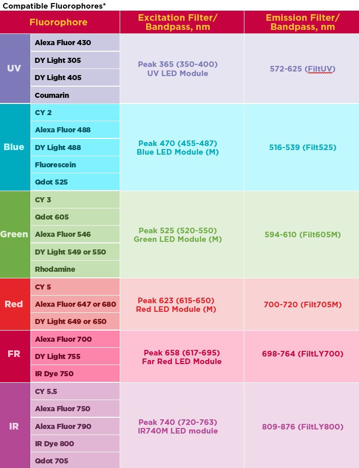
How do I know which HiLED and filter I need to image my fluorescent blot?
It can be tricky to know which HiLED module to use and which emission filter to pair it with to detect the fluorescent signal. But do not worry. Below we have put together a handy table that you can use! We have listed the more commonly used fluorescent dyes, but if the fluorescent dye you are using isn’t listed below, please contact us at Syngene, as we will be happy to help you find the right imaging set-up for an experiment.
How to avoid crosstalk when multiplexing several fluorescent dyes at the same time?
What is crosstalk, and how can I prevent it? Each fluorescent dye has an excitation and emission spectral curve. There are several tools available to be able to view the spectral curves of commercially available fluorescent dyes. For example, the ThermoFisher Fluorescence SpectraViewer lets you view several fluorescent dye excitation and emission spectra on the same graph to determine any spectral overlap between the selected fluorophores. This spectral overlap is called crosstalk, and to be able to minimise or remove crosstalk, you ideally need to have fluorophores used in the multiplex experiment to have distinct regions of either excitation or emission spectra that are compatible with the lights and filters in the imaging system. It is important to note that only a region of either the excitation or the emission spectrum needs to be distinct, not both.
An example of a commonly used fluorescence multiplex is to use Alexa Fluor 488, 546 and 647, so each fluorescent dye emits in a separate colour channel, Blue, Green and Red, respectively.
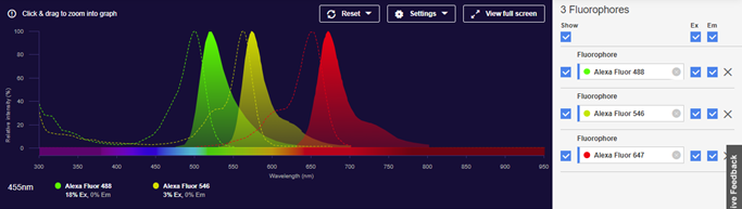
The image is taken from ThermoFisher Fluorescence spectral viewer.
The image above shows some spectral overlap between Alexa Fluor 488 and Alexa Fluor 546 and a small amount of spectral overlap between Alexa Fluor 546 and Alexa Fluor 647. At Syngene, we have spent much time considering the design of our lights and filters used in our systems to ensure minimal crosstalk when multiplexing.
The following image shows, for the example of the multiplex (AF488, 546 and 647), the bandpasses of the light sources and emission filters we recommend.
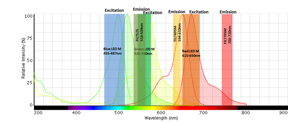
The emission of each fluorescent dye has no or minimal overlap within the ranges of the three emission filters despite each fluorophore having part of its excitation spectra within the range of the excitation filter.
Any Alexa Fluor 546 fluorescence generated by that excitation range is not within the wavelength range allowed to pass through the emission filter.
Our G:Box is perfect for western blot imaging, giving you more control over detecting proteins. This powerful system, powered by Syngene’s GeneSys software, lets you choose from various chemiluminescence and fluorescence reagents. You’ll get sharp, publication-quality images with minimal background interference. Find out more about our systems here https://www.syngene.com/product-category/chemiluminescence-fluorescence-systems/ or contact or contact our team directly at sales@syngene.com.